Assignment 8 - Bond Graphs#
In this assignment we will look at a wide range of bond graphs. In the first two problems we study how power bonds can be used to connect submodels into a full system model. Then, in the last three problems, we develop bond graphs for systems from different fields of engineering. We look at one mechanical system, one electrical system and one hydraulic system. Together with the first problems, the utlity of bond graphs becomes clear, namely that we can couple disparate engineering fields in the same framework using the same tools!
Problem 1 - Steering mechanism#

Fig. 23 Simple model of a steering mechanism.#

Fig. 24 Word bond graph for the steering mechanism.#
Figure Fig. 23 shows a simple model of a steering mechanism for a vehicle, while figure Fig. 24 shows a word bond graph for the same steering mechanism.
Tasks
Draw a block diagram of the system based on the word bond graph and the causality assignment given to it.
Hint
Recall that the causal stroke is on the submodel where the effort is input and the flow is output.
The following information is given about each submodel:
- Battery:
Gives a constant voltage.
- DC motor:
A DC-motor can be described by the following equations
(211)#\[\begin{split}L_a \frac{di_a}{dt} = -R_a i_a - K_t \omega_m + u_a \\ J \dot{\omega}_m = K_T i_a - \tau\end{split}\]where \(L_a\) is the armature inductance, \(i_a\) is the armature current, \(R_a\) is the resistance in the armature circuit, \(K_T\) is a constant, \(\omega_m\) is the speed of the motor, \(u_a\) is the armature voltage, and the torque \(\tau\) is the load.
- Flexible shaft:
A flexible shaft may have a slight difference in the angular velocity \(\omega_1\) and :math: omega_2 of each side, resulting also in a slight difference \(\Delta \theta = \int_{t_0}^t (\omega_2 - \omega_1) dt\) in the angular displacement on each side. We can think of the flexible shaft as an angular spring with a linear relation between the angular displacement and the torque, such that \(\tau = k_s \Delta \theta\). The moment of inertia for the shaft is small compared to the moment of inertia of the DC-motor and the rack, so we may consider it as massless.
- Gear (or pinion):
The gear is modelled as massless and loss-less (i.e. it does not remove energy from the system). Its function in this system is to transform between the angular velocity and torque on one port, and linear velocity and a force on the other port. The relationship between the linear velocity and the angular velocity is \(v = r\omega\). Since it is loss-less, we also have that the power on each port is identical. In equation form this can be stated as \(\omega \tau = v F\).
- Rack:
The rack can be modelled as mass m that can move with one degree of freedom. This mass is governed by the equation: \(ma = \sum F\) .
- Spring:
The spring gives a linear relation between the force and the displacement, such that the spring force \(F_s\) is given as \(F_s = kx\) , where \(x = \int_{t_0}^t v dt\).
- Damper:
The damper (or dashpot) is governed by the law: \(F_d = k_d v\).
Show that the system equations for the steering mechanism can be written as
(212)#\[\begin{split}L_a \frac{di_a}{dt} &= -R_a i_a - K_t \omega_1 + u_a \\ J \dot{\omega}_m &= K_T i_a - k_s \Delta \theta \\ \dot{\Delta \theta} &= \frac{1}{r} v - \omega_1 \\ \dot{x} &= v \\ m \dot{v} &= - kx - dv + \frac1{r} k_s \Delta \theta\end{split}\]Use the block diagram you made, the word bond graph and the information given above.
Hint
Recall that the direction of the half arrows in the word bond graph defines which direction of positive power (energy flow). This means that the half arrows will be useful in defining the sign of efforts and flows in the final set of differential equations.
Problem 2 (optional) - Two rotating shafts#
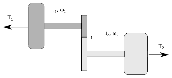
Fig. 25 Two rotating shafts connected by a gearbox#

Fig. 26 Word bond graph of the system#
Figure Fig. 25 shows two rotating flywheels connected by a gearbox. The gearbox is friction-less. There are two torques \(T_1\) and \(T_2\) applied to the two flywheels. The left flywheel rotates with the angular speed \(\omega_1\) and has moment of inertia \(J_1\), while the right-hand flywheel rotates with an angular speed \(\omega_2\) and has moment of inertia \(J_2\). A system model is shown in the form of a word bond graph in figure Fig. 26.
Tasks
Draw a block diagram for the system based on the word bond graph and the causality defined by the causal strokes.
While it is tempting to use two differential equations on the form
(213)#\[J_i \dot{\omega}_i = \sum T\]this is not viable because the two flywheels are not able to rotate independently of each other. If we know \(\omega_1\), we also know \(\omega_2\) (and if we know \(\dot{\omega_1}\) we know \(\dot{\omega_2}\)). In particular, \(r \omega_1 = \omega_2\) and \(\tau_1 = r \tau_2\). Therefore we only need a single differential equation to describe both of them. Show that the equation of motion for the two flywheels can be written as
(214)#\[\left( J_1 + r^2 J_2 \right) \dot{\omega}_1 = T_1 + r T_2\]Derive the same expression using Lagrange mechanics with your generalized coordinate \(q = \theta_1\) and \(\dot{q} = \omega_1\).
Problem 3 - Pendulum on an oscillator#

Fig. 27 Pendulum on a vertical oscillator.#
We will revisit the oscillating pendulum one last time. This time we will use bond graph to model the system.
Figure Fig. 27 shows a sketch of the system. A pendulum with a point mass \(m_2\) is attached to a mass \(m_1\) that can oscillate along a vertical axis. The pendulum rod has a length \(L\) and the rod can be considered mass-less (i.e. the pendulum can be considered as a point mass at the end of a mass-less rod).
The oscillating mass is connected to a stationary construction through a spring with stiffness \(k\). The vertical position \(z\) of the mass is defined such that \(z = 0\) when the spring is in its neutral position. The angular displacement of the pendulum rod is \(\theta\), as shown in the figure. For simplicity we also constrain body one to only move up or down, i.e no movement along the \(y_0\) or \(z_0\) axis.
Tasks
Draw a bond graph for the system, as described above. Include gravity force on the two masses.
Hint
A good starting point is to place a 1-junction for each relevant velocity. In this case, you will need a velocity representing the vertical movement of the oscillating mass, and two 1-junctions representing the horizontal velocity and the vertical velocity of the pendulum mass. In addition, you will need a 1 junction for \(\dot{\theta}\) because the vertical and horizontal velocity of the point mass on the pendulum is a function of \(\dot{\theta}\). You then need to establish a relationship between them using MTF-elements and 0-junctions.
Now include linear friction on the motion of oscillating mass and the pendulum hinge.
Assume now that the mass at the end of the pendulum is not a point mass but a sphere with mass \(m_2\) and moment of inertia of \(J_2\). Update the bond graph to account for this.
Problem 4 - Electrical circuit with a battery#

Fig. 28 Electrical circuit with a battery.#
Figure Fig. 28 show an electrical circuit powered by voltage source \(u(t)\). The task is to develop a bond graph for this system. The parameters for the two resistors, two capacitors and the inductance, are \(R_1\) and \(R_2\), \(C_1\) and \(C_2\), and \(L\) respectively.
Task
Draw a bond graph for the circuit.
Problem 5 - Single acting spring return hydraulic actuator#

Fig. 29 A single acting spring return hydraulic actuator powered by a hydraulic pump.#
Figure Fig. 29 shows a hydraulic system were fluid can be pumped from a reservoir and into to single acting hydraulic actuator, or back to the reservoir via a controllable valve. The opening area of the valve can be controlled though the signal \(u(t)\) to return fluid to the reservoir and hence reduce the pressure on the hydraulic actuator. When the pressure is low enough, the spring will return the hydraulic actuator piston back to the position \(x = 0\).
Task
Draw a bond graph for this system where \(P_a\) is the atmospheric pressure.